How to Tell Gravity Feed Carb From Nongravity Feed
The fuel system in a helicopter is made up of two groups of components:
- The fuel supply system
- The engine fuel control system.
The supply system consists of a fuel tank or tanks, fuel quantity gauges, a shut-off valve, fuel filter, a fuel line to the engine, and possibly a primer and fuel pumps. See figure 5-1.
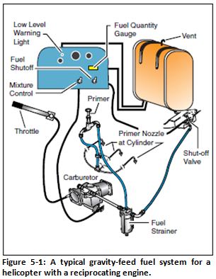 The fuel tanks are usually mounted to the airframe as close as possible to the center of gravity to minimize center of gravity change as fuel is burned. A drain valve located on the fuel tank bottom allows any collected water and sediment to be drained. A vent prevents vacuum formation and an overflow drain allows fuel to expand without rupturing the tank. A fuel quantity gauge shows the amount of fuel measured by a sensing unit inside the tank. The fuel travels from the fuel tank through a shut-off valve, which allows complete fuel flow shutoff to the engine in the event of an emergency or fire. Most non-gravity feed fuel systems contain both an electric pump and a mechanical engine driven pump. The electrical pump is used to maintain positive fuel pressure to the engine pump and also serves as a backup in the event of mechanical pump failure. The electrical pump is controlled by a switch in the cockpit. The engine driven pump is the primary pump that supplies fuel to the engine and operates any time the engine is running. A fuel filter removes any remaining moisture and other sediment from the fuel before it reaches the engine. Some fuel systems contain a small hand-operated pump called a primer. A primer allows fuel to be pumped directly into the intake port of the cylinders prior to engine start. The primer is useful in cold weather when fuel in the carburetor is difficult to vaporize.
The purpose of the fuel control system is to bring outside air into the engine, mix it with fuel in the proper proportion, and deliver it to the combustion chamber. Fuel is delivered to the cylinders by either a carburetor or fuel injection system.
In a carbureted system, air is mixed with vaporized fuel as it passes through a Venturi in the carburetor. The metered fuel/air mixture is then delivered to the cylinder intake. Carburetors are calibrated at sea level, and the correct fuel-to-air mixture ratio is established at that altitude with the mixture control set in the FULL RICH position. As air density decreases with increasing altitude, the mixture control is used to reduce the amount of fuel entering the system to maintain the correct fuel/air mixture. This adjustment often referred to as "leaning the mixture" and varies from one aircraft to another.
Note that most manufacturers do not recommend leaning helicopters in-flight. Most mixture adjustments are required during changes of altitude or during operations at airports with field elevations well above sea level. A mixture that is too rich can result in engine roughness and reduced power. The roughness normally is due lower temperatures in the cylinder inhibiting complete combustion of the fuel, causing spark plug fouling from excessive carbon buildup on the plugs. This condition may occur during the pre-takeoff run-up at high elevation airports and during climbs or cruise flight at high altitudes. Usually, you can correct the problem by leaning the mixture according to the flight manual. Failing to enrich the mixture during descent can result in the mixture being too lean, resulting high engine temperatures which can cause excessive engine wear or failure.
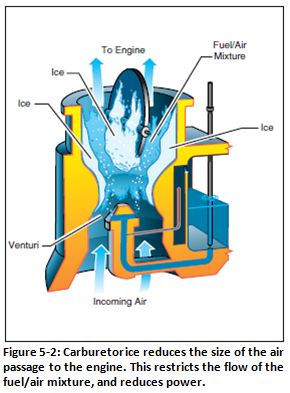
The effect of fuel vaporization and decreasing air pressure in the Venturi causes a sharp drop in temperature in the carburetor. If the air is moist, the water vapor in the air may condense. When the temperature in the carburetor is at or below freezing, carburetor ice may form on internal surfaces, including the throttle valve. See figure 5-2. The sudden cooling that takes place in the carburetor can cause icing to occur even on warm days with temperatures as high as 38°C (100°F) and the humidity as low as 50 percent. However, it is more likely to occur when temperatures are below 21°C (70°F) and the relative humidity is above 80 percent. The likelihood of icing increases as temperature decreases down to 0°C (32°F), and as relative humidity increases. Below freezing, the possibility of carburetor icing decreases with decreasing temperatures.
Although carburetor ice can occur during any phase of flight, it is particularly dangerous when you are using reduced power, such as during a descent. You may not notice it during the descent until you try to add power. Indications of carburetor icing are a decrease in engine RPM or manifold pressure, the carburetor air temperature gauge indicating a temperature outside the safe operating range, and engine roughness. Since changes in RPM or manifold pressure can occur for a number of reasons, it is best to closely check the carburetor air temperature gauge when in possible carburetor icing conditions. Carburetor air temperature gauges are marked with a yellow caution arc or green operating arcs. In most cases, temperature should be kept out of the yellow arc or in the green arc. This is accomplished by using a carburetor heat system, which eliminates the ice byrouting air across a heat source, such as an exhaust manifold, before it enters the carburetor.
In a fuel injection system, fuel and air are metered at the fuel control unit but are not mixed. The fuel is injected directly into the intake port of the cylinder where it is mixed with the air just before entering the cylinder. This system ensures a more even fuel distribution in the cylinders and better vaporization, which in turn, promotes more efficient use of fuel. Also, the fuel injection system eliminates the problem of carburetor icing and the need for a carburetor heat system.
The fuel control system on the turbine engine is fairly complex, as it monitors and adjusts many different parameters on the engine. These adjustments are done automatically and no action is required of the pilot other than starting and shutting down. No mixture adjustment is necessary, and operation is fairly simple as far as the pilot is concerned. New generation fuel controls incorporate the use of a full authority digital engine control (FADEC) computer to control the engine's fuel requirements. The FADEC systems increase efficiency, reduce engine wear, and also reduce pilot workload. The FADEC usually incorporates back-up systems in the event of computer failure.
Source: https://www.faasafety.gov/gslac/alc/course_content_popup.aspx?cID=105&sID=463
0 Response to "How to Tell Gravity Feed Carb From Nongravity Feed"
Post a Comment